On April 25, 2025, we received a special order from an old customer – a batch of high-performance 904L weld neck & blind flanges. This is not just a deal, but another confirmation of the long-term trust and tacit understanding between us and our customers.
This customer has always been very demanding on product quality and material performance, and this time chose 904L flanges because of its excellent performance and extraordinary durability in extremely corrosive environments. We are well aware that these flanges will become an indispensable “connection point” in their key projects, carrying the safe transportation of fluids and the stable operation of equipment.
904L is a high alloy austenitic stainless steel, known for its excellent corrosion resistance, especially in dealing with strong acidic environments (such as sulfuric acid, phosphoric acid) and chloride corrosion (pitting, crevice corrosion and stress corrosion cracking). Therefore, 904L flanges are important components for connecting critical piping systems to ensure long-term stable operation under harsh conditions.
Purchase List
| ITEM | Description | Quanitity | Unit |
| 1 | BLIND FLANGE, DN200 RF, PN16 ASTM A182 F-904L. FORGED.EN 1092 | 4 | EA |
| 2 | BLIND FLANGE,DN100 RF, PN10 ASTM A182 F-904L. FORGED. EN 1092 | 6 | EA |
| 3 | BLIND FLANGE, DN80 RF, PN10 ASTM A182 F-904L, FORGED, EN 1092 | 2 | EA |
| 4 | BLIND FLANGE, DN50 RF, PN10 ASTM A182 F-904L. FORGED. EN 1092 | 2 | EA |
| 5 | WNRF, DN100 SCh 10S, PN10 ASTM A182 F-904L, FORGED, EN 1092 | 6 | EA |
| 6 | WNRF, DN80 SCh 10S, PN10 ASTM A182 F-904L, FORGED, EN 1092 | 34 | EA |
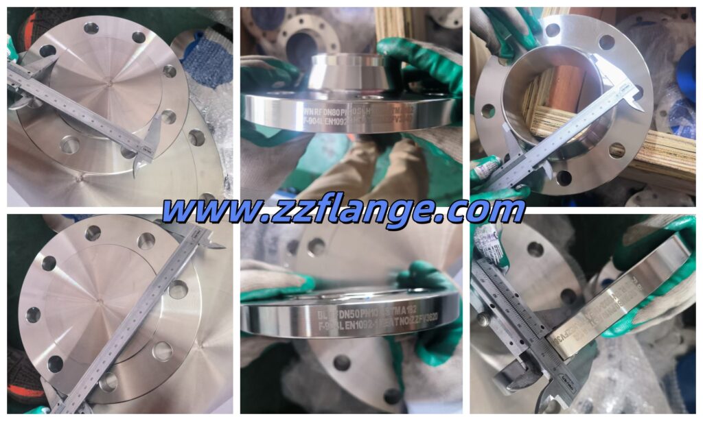
Dimensional Inspection of 904L Flange
- Outer Diameter
Ensure overall compatibility: Verify that the flange can be properly installed within the reserved space in the piping system without interference from surrounding equipment or structures. - Thickness
Ensure pressure resistance: Flange thickness is a critical factor in determining its pressure-bearing capacity. Sufficient thickness ensures the flange will not deform or crack under rated pressure, maintaining system sealing performance. - Sealing Face Diameter
Ensure sealing integrity: This is one of the most critical inspection points. The sealing face diameter must precisely match the selected gasket size to ensure uniform compression under pressure and form an effective seal to prevent fluid leakage. - Bolt Circle Diameter (BCD)
Ensure bolt hole alignment: This is a decisive factor for proper flange connection. An accurate bolt circle diameter ensures full alignment with the mating flange’s bolt holes, allowing bolts to pass through smoothly and be evenly stressed, avoiding damage from forced installation. - Number and Diameter of Bolt Holes
Ensure connection strength: The number and diameter of bolt holes must meet the standard to ensure enough bolts are available to bear the stress at the flange connection and to apply uniform preload on the gasket. - Pipe End Outside Diameter
Ensure match with pipe OD: This is the core objective. The outside diameter of the weld neck portion of the flange must closely match the pipe’s outside diameter to ensure proper alignment during welding, reduce misalignment, and achieve a high-quality weld joint.
Specification of Forged Steel Flange
| Shape Type | Regular and Long Neck |
| Sealing Face | RF, FF, FTJ |
| Size Range | 1/2″ – 48″/ DN15 – DN1200 |
| Pressure Rating | Class 150, 300, 600, 900, 1500, 2500lb |
| Standard | ASME B16.5, ASME B16.47 Series A/B |
| Stainless Steel | ASTM A182 F304/304L/304H, 316/316L, 310S, 317,347,904L |
ASTM A182 F904L Flange Chemical Composition
| CHEMICAL | LIMITS | C | Mn | P | S | Si | Ni | Cr | Mo | N | Ti | Cu |
| ASTM A182 F904L (N08904) | MIN | 23 | 19 | 4 | 1 | |||||||
| MAX | 0.02 | 2 | 0.04 | 0.03 | 1 | 28 | 23 | 5 | 0.1 | 2 |
ASTM A182 F904L Flange Mechanical Property
| MATERIAL | T.S (MPA) | Y.S (MPA) | EL % |
| ASTM A182 F904L | 490 min | 215 min | 35 min |
PN16 Forged Flange Dimensions
| Table 13 — Dimensions of PN 16 flanges | |||||||||||||||||||||||||||||||
| Dimensions in millimetres | |||||||||||||||||||||||||||||||
| DN | Mating dimensions | Outside diameter of neck | Bore diameters | Flange thickness | Chamfer | Collar thickness | Centre portion | Length | Neck diameters | Corner radii | Wall thickness (see 5.6.1) | ||||||||||||||||||||
| Outside diameter | Diameter of bolt circle | Diameter of bolt hole | Bolting | ||||||||||||||||||||||||||||
| D | K | L | Number | Size | A | B1 | B2 | B3 | C1 | C2 | C3 | C4 | E | F | Gmax | H1 | H2 | H3 | H4 | H5 | N1 | N2 | N3 | R1 | S | ||||||
| Flange type | |||||||||||||||||||||||||||||||
| 01, 02, 04, 05, 11, 12, 13, 21 | 11 21 a 34 d 35 – 37 | 01 12 32 | 02 | 04 | 01 02 04 | 11 12 13 | 21 | 05 | 02 04 | 32 34 d | 35 | 36 | 37 | 05 | 12 13 | 11 34 c,d | 11 34 c,d | 35 | 36 | 37 | 11 34 c, d | 12 13 | 21 | 11 12 13 21, 34d | 34 d | 11, 35 to 37 | |||||
| 10 | 90 | 60 | 14 | 4 | M12 | 172 | 180 | 21 | 31 | 14 | 16 | 16 | 16 | 3 | 12 | 5 | 2 | 25 | 22 | 35 | 6 | 35 | 35 | 7 | 28 | 30 | 28 | 4 | 18 | See Annex A | |
| 15 | 95 | 65 | 14 | 4 | M12 | 213 | 220 | 25 | 35 | 14 | 16 | 16 | 16 | 3 | 12 | 5 | 2 | 25 | 22 | 38 | 6 | 38 | 38 | 7 | 32 | 35 | 32 | 4 | 20 | ||
| 20 | 105 | 75 | 14 | 4 | M12 | 269 | 275 | 31 | 42 | 16 | 18 | 18 | 18 | 4 | 14 | 6 | 25 | 3 | 26 | 40 | 6 | 40 | 40 | 8 | 40 | 45 | 40 | 4 | 23 | ||
| 25 | 115 | 85 | 14 | 4 | M12 | 337 | 345 | 38 | 49 | 16 | 18 | 18 | 18 | 4 | 14 | 7 | 25 | 3 | 28 | 40 | 6 | 40 | 40 | 10 | 46 | 52 | 50 | 4 | 26 | ||
| 32 | 140 | 100 | 18 | 4 | M16 | 424 | 435 | 47 | 59 | 18 | 18 | 18 | 18 | 5 | 14 | 8 | 3 | 3 | 30 | 42 | 6 | 42 | 42 | 12 | 56 | 60 | 60 | 6 | 26 | ||
| 40 | 150 | 110 | 18 | 4 | M16 | 483 | 495 | 53 | 67 | 18 | 18 | 18 | 18 | 5 | 14 | 8 | 3 | 3 | 32 | 45 | 7 | 45 | 45 | 15 | 64 | 70 | 70 | 6 | 26 | ||
| 50 | 165 | 125 | 18 | 4 | M16 | 603 | 615 | 65 | 77 | 20 | 18 | 18 | 18 | 5 | 16 | 8 | 3 | 3 | 28 | 45 | 8 | 45 | 45 | 20 | 74 | 84 | 84 | 6 | 29 | ||
| 65 | 185 | 145 | 18 | 8b | M16 | 761 | 775 | 81 | 96 | 20 | 18 | 18 | 18 | 6 | 16 | 8 | 3 | 3 | 55 | 32 | 45 | 10 | 45 | 45 | 20 | 92 | 104 | 104 | 6 | 29 | |
| 80 | 200 | 160 | 18 | 8 | M16 | 889 | 905 | 94 | 108 | 20 | 20 | 20 | 20 | 6 | 16 | 10 | 3 | 3 | 70 | 34 | 50 | 10 | 50 | 50 | 25 | 105 | 118 | 120 | 6 | 32 | |
| 100 | 220 | 180 | 18 | 8 | M16 | 1,143 | 1,160 | 120 | 134 | 22 | 20 | 20 | 20 | 6 | 18 | 10 | 4 | 4 | 90 | 40 | 52 | 12 | 52 | 52 | 25 | 131 | 140 | 140 | 8 | 36 | |
| 125 | 250 | 210 | 18 | 8 | M16 | 1,397 | 1,415 | 145 | 162 | 22 | 22 | 22 | 22 | 6 | 18 | 10 | 4 | 4 | 115 | 44 | 55 | 12 | 55 | 55 | 25 | 156 | 168 | 170 | 8 | 40 | |
| 150 | 285 | 240 | 22 | 8 | M20 | 1,683 | 1,705 | 174 | 188 | 24 | 22 | 22 | 22 | 6 | 20 | 10 | 5 | 5 | 140 | 44 | 55 | 12 | 55 | 55 | 25 | 184 | 195 | 190 | 10 | 45 | |
| 200 | 340 | 295 | 22 | 12 | M20 | 2,191 | 2,215 | 226 | 240 | 26 | 24 | 24 | 24 | 6 | 20 | 11 | 6 | 6 | 190 | 44 | 62 | 16 | 62 | 62 | 30 | 235 | 246 | 246 | 10 | 63 | |
| 250 | 405 | 355 | 26 | 12 | M24 | 2,730 | 2,765 | 281 | 294 | 29 | 26 | 26 | 26 | 8 | 22 | 12 | 10 | 235 | 46 | 70 | 16 | 70 | 68 | 292 | 298 | 296 | 12 | 63 | |||
| 300 | 460 | 410 | 26 | 12 | M24 | 3,239 | 3,275 | 333 | 348 | 32 | 28 | 28 | 28 | 8 | 24 | 14 | 10 | 285 | 46 | 78 | 16 | 78 | 68 | 344 | 350 | 350 | 12 | 71 | |||
| 350 | 520 | 470 | 26 | 16 | M24 | 3,556 | 3,595 | 365 | 400 | 35 | 30 | 30 | 30 | 8 | 26 | 18 | 10 | 330 | 57 | 82 | 16 | 82 | 68 | 390 | 400 | 410 | 12 | 80 | |||
Applications of 904L Weld Neck & Blind Flanges
Sulfuric acid treatment and production
Seawater and brine treatment
Marine engineering and offshore platforms
Desalination plants
Coastal power plants
Pollution control equipment
Flue gas desulfurization (FGD) systems
Chemical and petrochemical industries:
Pharmaceutical industry
Food and beverage industry
Pulp and paper industry