In industrial piping systems, flanges serve as core connecting components whose quality and standardization directly impact system safety, sealing integrity, and service life. The EN1092-1 Flange (European Standard EN1092-1 Flange) has become the preferred choice globally across chemical, energy, and water treatment sectors due to its stringent manufacturing specifications, broad compatibility, and reliable performance. This article comprehensively analyzes EN1092-1 Flanges from dimensions including core standard content, product advantages, application scenarios, and selection techniques, empowering enterprises and purchasers to accurately choose compatible products.
EN 1092-1, developed by the European Committee for Standardization (CEN), is the standard for “Flanges and their joints – Part 1: Steel flanges.” It aims to unify the design, materials, dimensions, pressure ratings, and connection methods for steel flanges across Europe and globally, addressing compatibility issues between products from different regions.
EN 1092-1 flanges are applicable to steel piping systems with PN pressure ratings (PN2.5 to PN400) and Class pressure ratings (Class 150 to Class 2500), compatible with various materials including carbon steel, stainless steel, and alloy structural steel. The standard explicitly specifies chemical compositions, mechanical properties (such as tensile strength and yield strength), and heat treatment requirements for different materials, ensuring flange stability under high-temperature, high-pressure, and corrosive conditions.
We have completed orders for EN1092-1 flanges. For more details, please click
EN 1092-1 Flange Specification
| Standard | EN 1092-1 European Standard |
| Manufacturing Process | Hot Forging / Steel Casting / Hot Rolled / Plate Machining |
| Outer Diameter | DN 15 to DN 4000 |
| Pressure Class | PN 2.5, PN 6, PN 8, PN 10, PN 16, PN 25, PN 40, PN 63, PN 100 etc |
| Flanges Facing | Type Flat Face (FF), Type B Raised Face (RF), Type C Tongue, Type D Groove, Type E Spigot, Type F Recess, Type G O-ring Spigot, Type H O-ring Groove, |
EN 1092-1 Standard Scope
This European Standard for a single series of flanges specifies requirements for circular steel flanges in PN designations PN 2,5 to PN 400 and nominal sizes from DN 10 to DN 4000.
This European Standard specifies the flange types and their facings, dimensions, tolerances, threading, bolt sizes, flange jointing face surface finish, marking, materials, pressure/ temperature ratings and approximate flange masses.
For the purpose of this European Standard, “flanges” include also lapped ends and collars.
This European Standard applies to flanges manufactured in accordance with the methods described in Table 1.
Non-gasketed pipe joints are outside the scope of this European Standard
Bolting
Flanges shall be suitable for use with the number and size of bolting as specified in Table 10 to Table 21. The bolting shall be chosen by the equipment manufacturer according to the pressure, temperature, flange material and gasket so that the flanged joint remains tight under the expected operating conditions. For selection of bolting, see EN 1515-4, for combination of the materials of flanges and bolting see EN 1515-2, for information.
Gaskets
The various gasket types, dimensions, design characteristics and materials used are not within the scope of this European Standard. Dimensions of gaskets are given in the EN 1514 series.
Terms and definitions
For the purposes of this document, the following terms and definitions apply.
DN
alphanumeric designation of size for components of a pipework system, which is used for reference purposes and which comprises the letters DN followed by a dimensionless whole number that is indirectly related to the physical size, in millimetres, of the bore or outside diameter of the end connections
Note 1 to entry: The number following the letters DN does not represent a measurable value and should not be used for calculation purposes except where specified in the relevant standard.
Note 2 to entry: In those standards which use the DN designation system, any relationship between DN and component dimensions should be given, e.g. DN/OD or DN/ID.
PN
alphanumeric designation which is used for reference purposes related to a combination of mechanical and dimensional characteristics of a component of a pipework system and which comprises the letters PN followed by a dimensionless number
Note 1 to entry: The number following the letters PN does not represent a measurable value and should not be used for calculation purposes except where specified in the relevant standard.
Note 2 to entry: The designation PN is not meaningful unless it is related to the relevant component standard number.
Note 3 to entry: The maximum allowable pressure of a pipework component depends on the PN number, the material and the design of the component, its maximum allowable temperature, etc. The relevant European Component standards include tables of specified pressure/temperature ratings or, in minimum, include rules how to determine pressure/temperature ratings.
Note 4 to entry: It is intended that all components with the same PN and DN designations have the same mating dimensions for compatible flange types.
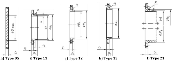
EN1092-1 Flange Types

| Flanges Types | |
| Type 01 | Plate Flange for welding, |
| Type 02 | Loose Plate Flange with Weld-on Plate Collar or for Lapped Pipe End, |
| Type 04 | Loose Plate Flange with weld-neck collar, |
| Type 05 | Blind Flange, |
| Type 11 | Weld-neck Flange, |
| Type 12 | Hubbed Slip-on Flange for welding, |
| Type 13 | Hubbed Threaded Flange, |
| Type 34 | Weld-neck collar Flange, |
| Type 35 | Weldring neck Flange, |
| Type 36 | Pressed collar with long neck Flange, |
| Type 37 | Pressed collar Flange, |
Dimensions of EN 1092-1 Flange PN6

| DN | Mating dimensions | Outside diameter of neck A | Bore diameters | Flange thickness | Chamfer E | Collar thickness F | Centre portion Gmax | Length | Neck diameters | Corner radii Ri | |||||||||||||||||
| Outside diameter D | Diameter of bolt circle K | Diameter of bolt hole L | Bolting | ||||||||||||||||||||||||
| Number | Size | B1 | B₂ | C₁ | C₂ C₃ | C4 | H₁ | H₂ | H₃ | H₄ | H₅ | N₁ | N₂ | N₃ | |||||||||||||
| Flange type | |||||||||||||||||||||||||||
| 01,02,05,11,12,13,21 | 11 21a 35-37 | 01 12 32 | 02 | 01 02 | 11 12 13 21 | 05 | 02 | 32 | 35 | 36 | 37 | 05 | 12 13 | 11 | 11 | 35 | 36 | 37 | 11 | 12 13 | 21 | 11 12 13 21 | |||||
| 10 | 75 | 50 | 11 | 4 | M10 | 17.2 | 18.0 | 21 | 12 | 12 | 12 | 3 | 10 | 5 | 2 | 25 | 一 | 20 | 28 | 6 | 28 | 35 | 7 | 26 | 25 | 20 | 4 |
| 15 | 80 | 55 | 11 | 4 | M10 | 21.3 | 22.0 | 25 | 12 | 12 | 12 | 3 | 10 | 5 | 2 | 25 | 一 | 20 | 30 | 6 | 30 | 38 | 7 | 30 | 30 | 26 | 4 |
| 20 | 90 | 65 | 11 | 4 | M10 | 26.9 | 27.5 | 31 | 14 | 14 | 14 | 4 | 10 | 6 | 25 | 3 | 一 | 24 | 32 | 6 | 32 | 40 | 8 | 38 | 40 | 34 | 4 |
| 25 | 100 | 75 | 11 | 4 | M10 | 33.7 | 34.5 | 38 | 14 | 14 | 14 | 4 | 10 | 7 | 25 | 3 | 一 | 24 | 35 | 6 | 35 | 40 | 10 | 42 | 50 | 44 | 4 |
| 32 | 120 | 90 | 14 | 4 | M12 | 42.4 | 43.5 | 46 | 16 | 14 | 14 | 5 | 10 | 8 | 3 | 3 | 一 | 26 | 35 | 6 | 35 | 42 | 12 | 55 | 60 | 54 | 6 |
| 40 | 130 | 100 | 14 | 4 | M12 | 48.3 | 49.5 | 53 | 16 | 14 | 14 | 5 | 10 | 8 | 3 | 3 | 一 | 26 | 38 | 7 | 38 | 45 | 15 | 62 | 70 | 64 | 6 |
| 50 | 140 | 110 | 14 | 4 | M12 | 60.3 | 61.5 | 65 | 16 | 14 | 14 | 5 | 12 | 8 | 3 | 3 | 一 | 28 | 38 | 8 | 38 | 45 | 20 | 74 | 80 | 74 | 6 |
| 65 | 160 | 130 | 14 | 4 | M12 | 76.1 | 77.5 | 81 | 16 | 14 | 14 | 6 | 12 | 8 | 3 | 3 | 55 | 32 | 38 | 9 | 38 | 45 | 20 | 88 | 100 | 94 | 6 |
| 80 | 190 | 150 | 18 | 4 | M16 | 88.9 | 90.5 | 94 | 18 | 16 | 16 | 6 | 12 | 10 | 3 | 3 | 70 | 344 | 42 | 10 | 42 | 50 | 25 | 102 | 110 | 110 | 8 |
| 100 | 210 | 170 | 18 | 4 | M16 | 114.3 | 116.0 | 120 | 18 | 16 | 16 | 6 | 14 | 10 | 4 | 4 | 90 | 40 | 45 | 10 | 45 | 52 | 25 | 130 | 130 | 130 | 8 |
| 125 | 240 | 200 | 18 | 8 | M16 | 139.7 | 141.5 | 145 | 20 | 18 | 18 | 6 | 14 | 10 | 4 | 4 | 115 | 44 | 48 | 10 | 48 | 55 | 25 | 155 | 160 | 160 | 8 |
| 150 | 265 | 225 | 18 | 8 | M16 | 168.3 | 170.5 | 174 | 20 | 18 | 18 | 6 | 14 | 10 | 5 | 4 | 140 | 44 | 48 | 12 | 48 | 55 | 25 | 184 | 185 | 182 | 10 |
| 200 | 320 | 280 | 18 | 8 | M16 | 219.1 | 221.5 | 226 | 22 | 20 | 20 | 6 | 16 | 11 | 5 | 5 | 190 | 44 | 55 | 15 | 55 | 62 | 30 | 236 | 240 | 238 | 10 |
| 250 | 375 | 335 | 18 | 12 | M16 | 273.0 | 276.5 | 281 | 24 | 22 | 22 | 8 | 18 | 12 | 8 | 235 | 44 | 60 | 15 | 60 | 68 | 一 | 290 | 295 | 284 | 12 | |
| 300 | 440 | 395 | 22 | 12 | M20 | 323.9 | 327.5 | 333 | 24 | 22 | 22 | 8 | 18 | 12 | 8 | 285 | 44 | 62 | 15 | 62 | 68 | 一 | 342 | 355 | 342 | 12 | |
| 350 | 490 | 445 | 22 | 12 | M20 | 355.6 | 359.5 | 365 | 26 | 22 | 22 | 8 | 18 | 13 | 8 | 330 | 一 | 62 | 15 | 62 | 68 | 一 | 385 | 一 | 392 | 12 | |
| 400 | 540 | 495 | 22 | 16 | M20 | 406.4 | 411.0 | 416 | 28 | 22 | 22 | 8 | 20 | 14 | 8 | 380 | 一 | 65 | 15 | 65 | 72 | 一 | 438 | 一 | 442 | 12 | |
| 450 | 595 | 550 | 22 | 16 | M20 | 457.0 | 462.0 | 467 | 30 | 22 | 24 | 8 | 20 | 15 | 8 | 一 | 425 | 一 | 65 | 15 | 72 | 72 | 一 | 492 | 一 | 494 | 12 |
| 500 | 645 | 600 | 22 | 20 | M20 | 508.0 | 513.5 | 519 | 30 | 24 | 24 | 8 | 22 | 16 | 8 | 一 | 475 | 一 | 68 | 15 | 75 | 75 | 一 | 538 | 一 | 544 | 12 |
| 600 | 755 | 705 | 26 | 20 | M24 | 610.0 | 616.5 | 622 | 32 | 30 | 30 | 8 | 22 | 16 | 一 | 一 | 575 | 一 | 70 | 16 | 70 | 一 | 一 | 640 | 一 | 642 | 12 |
| a For fanges type 21 the outside hub diameter aproximately corresponds to te ouside pipe diameter and the nominal value dimensions A,N3 and R1 and their tlerances are included for guidance only. b To be specified by the purchaser. | |||||||||||||||||||||||||||
Click here for full dimensions of EN1092-1 flanges
Characteristics of EN 1092-1 Flanges
✅ Standardized dimensions: Ensures global interchangeability and compatibility
✅ Diverse sealing surfaces: Accommodates varying pressure and medium requirements
✅ Extensive pressure ratings: Suitable for low-, medium-, and high-pressure piping systems
✅ Multiple material options: Carbon steel, stainless steel, alloy steel, copper-nickel alloys, etc.
✅ Extensive Applications: Covering energy, chemical, shipbuilding, environmental protection, construction, and other industries
Application Fields of EN 1092-1 Flanges
EN 1092-1 flanges are suitable for nearly all industrial piping systems, with typical applications including:
Oil and gas transportation and refining
Chemical and petrochemical equipment
Desalination and shipbuilding
Power plant and boiler piping
Water treatment and heating systems
Why Choose Our EN 1092-1 Flanges?
We supply the full range of EN 1092-1 flanges, offering:
Dimensions and tolerances strictly compliant with EN standards
100% pre-shipment inspection with Material Test Certificate (MTC EN 10204 3.1/3.2)
Export-ready for global markets including Europe, Middle East, and Southeast Asia
Customization services: Special dimensions, surface treatments, anti-corrosion coatings
Frequently Asked Questions (FAQ)
Q: What is the difference between EN 1092-1 and ASME B16.5?
A: EN 1092-1 is a European standard that uses PN (nominal pressure) ratings and metric units. ASME B16.5 is an American standard that uses Class ratings and imperial units. They differ significantly in dimensions, pressure ratings, and design and are not interchangeable.
Q: How do I select the appropriate flange?
A: When selecting a flange, you need to consider the following key factors:
Pipe Size: The nominal diameter (DN) of the flange must match the pipe.
Pressure and Temperature: Choose a PN rating and material that meets the operating pressure and temperature of the piping system.
Medium: Consider the corrosiveness of the medium and select corrosion-resistant materials.
Connection Method: Select the flange type based on the connection method, such as welded, threaded, or loose-fitting.