On June 6, 2025, our domestic long-term customer sent us a quotation request for carbon & stainless steel flange, including weld neck flanges and socket weld flanges, covering multiple specifications and pressure ratings. Upon receiving the request, we immediately confirmed the product specifications and calculated the costs, and provided the customer with a detailed quotation and delivery schedule on the same day. The client expressed satisfaction with our response speed and technical support and placed an official order one month later.
ZIZI is a professional manufacturer specializing in the production and processing of pipes and fittings. Our pipes and pipe fittings are primarily used in industries such as chemicals, petroleum, natural gas, water conservancy, power, and marine engineering. Our product range includes various sizes of seamless pipes, welded pipes, butt-welded pipe fittings, high-pressure forged pipe fittings, and flanges. Materials used include carbon steel, stainless steel, alloy steel, low-temperature steel, duplex steel, and base alloys.Welcome to contact us.
Products Lists
| ITEM | Description | Quantity | Units |
| 1 | WN RF CL150 A105 ASME B16.5 SCH80 | 14 | piece |
| 2 | WN RF CL150 A105 ASME B16.5 XXS | 10 | piece |
| 3 | WN RF CL150 A105 ASME B16.5 SCH80 | 17 | piece |
| 4 | WN RF CL150 A182-F51 ASME B16.5 SCH40S | 10 | piece |
| 5 | WN RF CL300 A182-F316L ASME B16.5 SCH80S | 40 | piece |
| 6 | WN RF CL300 A182-F316L ASME B16.5 SCH40S | 11 | piece |
| 7 | SW RF CL150 A182-F316L ASME B16.5 | 4 | piece |
| 8 | SW RF CL150 A105 ASME B16.5 SCH160 | 6 | piece |
| 9 | SW RF CL150 A105 ASME B16.5 XXS | 6 | piece |
| 10 | SW RF CL300 A182-F316L ASME B16.5 SCH80S | 6 | piece |
| 11 | SW RF CL300 A182-F316L ASME B16.5 SCH80S | 12 | piece |
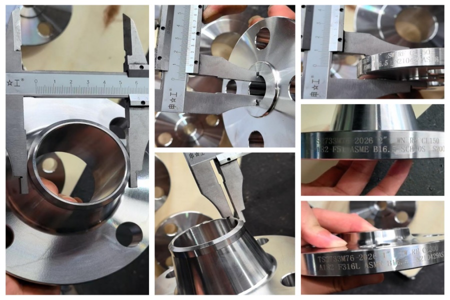
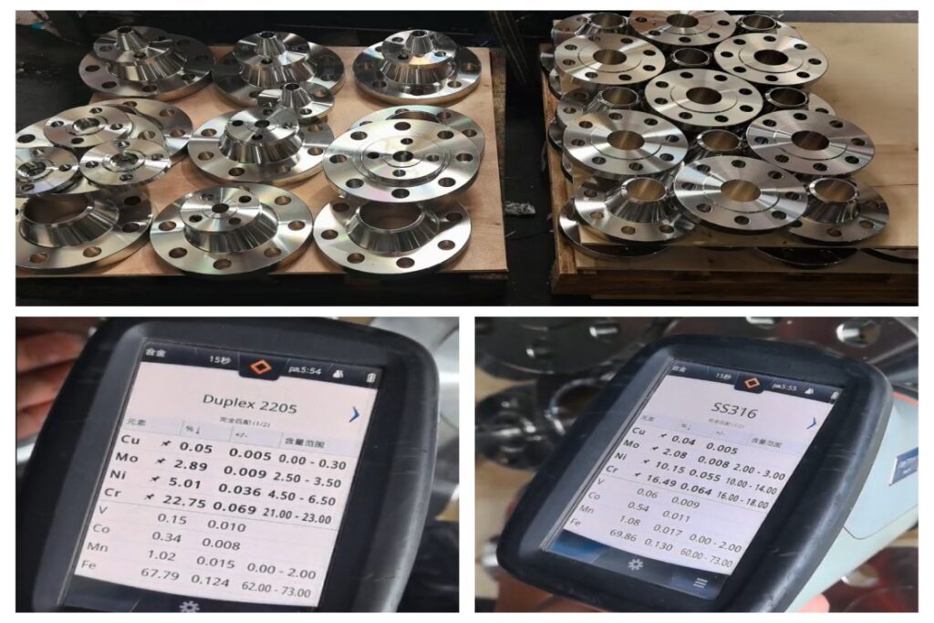
Inspection Photos
ASME B16.5 Forged Flange Specification
| Size: | 1/2 to 24 Inch / DN15 — DN600 |
| Pressure: | Class 150, 300, 600, 900, 1500, 2500 |
| Seal Type: | Raised Face (RF), Ring Type Joint (RTJ), Flat Face (FF) |
| Seal Thickness: | Sch 10S, 20, STD, 40, XS, 80, 160, XXS |
| Alloy Steel: | ASTM A182 F1, F5, F9, F11, F12, F22, F91 |
| Carbon Steel: | ASTM A105, A350 LF2,LF3. A694 F52, F60, F65, F70 |
| Stainless Steel: | ASTM A182 F304, F316, F317, F321, F310 |
| Duplex Stainless Steel: | ASTM A182 F51, F53, F55 |
| Product: | Weld Neck Flange, Socket Weld Flange, Threaded Flange, Blind Flange, Spectacle Blind, Slip On Flange, Ring Joint Flange, Plate Flange. |
ASTM A105 Carbon Steel Flange Chemical Composition
| CHEMICAL | LIMITS | C | Mn | P | S | Si | Cu | Ni | Cr | Mo | V |
| ASTM A105 | MIN | 0.60 | 0.10 | ||||||||
| MAX | 0.35 | 1.05 | 0.035 | 0.040 | 0.35 | 0.40 | 0.40 | 0.30 | 0.12 | 0.08 | |
| ASTM A105N | MIN | 0.600 | |||||||||
| MAX | 0.350 | 1.050 | 0.040 | 0.050 | 0.400 | 0.300 | 0.120 | 0.080 |
ASTM A105 Carbon Steel Flange Mechanical Property
| MATERIAL | T.S (MPA) | Y.S (MPA) | EL % | R/A % | HARDNESS |
| ASTM A105 | 485 min | 250 min | 22 min | 30 min | 197 max |
| ASTM A105N | 485min | 250 min | 22 min | 30 min | 197 max |
ASTM A182 F316L Flange Chemical Composition
| CHEMICAL | LIMITS | C | Mn | P | S | Si | Ni | Cr | Mo | N |
| ASTM A182 F316 | MIN | 10.0 | 16.0 | 2.00 | ||||||
| MAX | 0.08 | 2.00 | 0.045 | 0.030 | 1.00 | 14.0 | 18.0 | 3.00 | 0.10 | |
| ASTM A182 F316L | MIN | 10.00 | 16.0 | 2.00 | ||||||
| MAX | 0.03 | 2.00 | 0.045 | 0.030 | 1.00 | 15.00 | 18.0 | 3.00 | 0.10 |
ASTM A182 F316L Flange Mechanical Property
| MATERIAL | ASTM A182 F316 | ASTM A182 F316L |
| T.S (MPA) | 515 min | 485 min |
| Y.S (MPA) | 205 min | 170 min |
| EL % | 30 min | 30 min |
| R/A % | 50 min | 50 min |
ASTM A182 F51 Flange Chemical Composition
| CHEMICAL | LIMITS | C | Mn | P | S | Si | Ni | Cr | Mo | N |
| ASTM A182 F51 | MIN | 4.50 | 21.00 | 2.50 | 0.08 | |||||
| MAX | 0.03 | 2.00 | 0.030 | 0.020 | 1.00 | 6.50 | 23.00 | 3.50 | 0.20 |
ASTM A182 F51 Flange Mechanical Property
| MATERIAL | T.S (MPA) | Y.S (MPA) | EL % | R/A % |
| ASTM A182 F51 | 620 min | 450 min | 25 min | 45 min |
Class 150 Flange Dimension
| Nominal Pipe Size, NPS | Outside Diameter of Flange, O | Minimum Thickness of Flange, tf [Notes(2)-(4)] | Minimum Thickness Lap Joint, tf | Diameter of Hub, X | Hub Diameter Beginning of Chamfer Welding Neck, Ah [Note (5)] | Length Through Hub | Minimum Thread Length Threaded, T [Note (6)] | Bore | Corner Bore Radius of Lapped Flange and Pipe, r | Depth of Socket, D | ||||
| Threaded/ Slip-on/ Socket Welding, Y | Lapped, Y | Welding Neck, Y | Minimum Slip-on/ Socket Welding, B | Minimum Lapped, B | Welding Neck/ Socket Welding, B [Note (7)] | |||||||||
| 1/2 | 90 | 9.6 | 11.2 | 30 | 21.3 | 14 | 16 | 46 | 16 | 22.2 | 22.9 | 15.8 | 3 | 10 |
| 3/4 | 100 | 11.2 | 12.7 | 38 | 26.7 | 14 | 16 | 51 | 16 | 27.7 | 28.2 | 20.9 | 3 | 11 |
| 1 | 110 | 12.7 | 14.3 | 49 | 33.4 | 16 | 17 | 54 | 17 | 34.5 | 34.9 | 26.6 | 3 | 13 |
| 1 1/4 | 115 | 14.3 | 15.9 | 59 | 42.2 | 19 | 21 | 56 | 21 | 43.2 | 43.7 | 35.1 | 5 | 14 |
| 1 1/2 | 125 | 15.9 | 17.5 | 65 | 48.3 | 21 | 22 | 60 | 22 | 49.5 | 50.0 | 40.9 | 6 | 16 |
| 2 | 150 | 17.5 | 19.1 | 78 | 60.3 | 24 | 25 | 62 | 25 | 61.9 | 62.5 | 52.5 | 8 | 17 |
| 2 1/2 | 180 | 20.7 | 22.3 | 90 | 73.0 | 27 | 29 | 68 | 29 | 74.6 | 75.4 | 62.7 | 8 | 19 |
| 3 | 190 | 22.3 | 23.9 | 108 | 88.9 | 29 | 30 | 68 | 30 | 90.7 | 91.4 | 77.9 | 10 | 21 |
| 3 1/2 | 215 | 22.3 | 23.9 | 122 | 101.6 | 30 | 32 | 70 | 32 | 103.4 | 104.1 | 90.1 | 10 | … |
| 4 | 230 | 22.3 | 23.9 | 135 | 114.3 | 32 | 33 | 75 | 33 | 116.1 | 116.8 | 102.3 | 11 | … |
| 5 | 255 | 22.3 | 23.9 | 164 | 141.3 | 35 | 36 | 87 | 36 | 143.8 | 144.4 | 128.2 | 11 | … |
| 6 | 280 | 23.9 | 25.4 | 192 | 168.3 | 38 | 40 | 87 | 40 | 170.7 | 171.4 | 154.1 | 13 | … |
| 8 | 345 | 27.0 | 28.6 | 246 | 219.1 | 43 | 44 | 100 | 44 | 221.5 | 222.2 | 202.7 | 13 | … |
| 10 | 405 | 28.6 | 30.2 | 305 | 273.0 | 48 | 49 | 100 | 49 | 276.2 | 277.4 | 254.6 | 13 | … |
| 12 | 485 | 30.2 | 31.8 | 365 | 323.8 | 54 | 56 | 113 | 56 | 327.0 | 328.2 | 304.8 | 13 | … |
| 14 | 535 | 33.4 | 35.0 | 400 | 355.6 | 56 | 79 | 125 | 57 | 359.2 | 360.2 | Note(8) | 13 | … |
| 16 | 595 | 35.0 | 36.6 | 457 | 406.4 | 62 | 87 | 125 | 64 | 410.5 | 411.2 | Note(8) | 13 | … |
| 18 | 635 | 38.1 | 39.7 | 505 | 457.0 | 67 | 97 | 138 | 68 | 461.8 | 462.3 | Note(8) | 13 | … |
| 20 | 700 | 41.3 | 42.9 | 559 | 508.0 | 71 | 103 | 143 | 73 | 513.1 | 514.4 | Note(8) | 13 | … |
| 24 | 815 | 46.1 | 47.7 | 663 | 610.0 | 81 | 111 | 151 | 83 | 616.0 | 616.0 | Note(8) | 13 | … |
How to Choose?
When selecting carbon steel flanges and stainless steel flanges, the following factors should be primarily considered:
Medium characteristics: If the fluid is a corrosive medium (such as acids or alkalis), stainless steel flanges must be selected. If the medium is ordinary water or oil, carbon steel flanges are more cost-effective.
Environmental conditions: If the flange is installed in a corrosive environment such as a humid or high-salt fog environment, stainless steel flanges provide better protection and reduce maintenance costs.
Budget: Under the premise of meeting performance requirements, if the budget is limited, carbon steel flanges are an economical choice.
Sanitary requirements: In the food and pharmaceutical industries, for sanitary reasons, only stainless steel flanges are typically permitted.