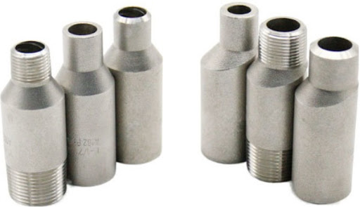
Swage nipple, also known as reducing fittings, are an important type of forged pipe fitting. In industrial piping systems, when it is necessary to connect two pipes of different sizes to achieve a change in pipe diameter, swage nipples play a critical role. The primary function of an eccentric reducer is to connect pipes of different sizes, with its design typically aimed at achieving a change in pipe diameter over a short distance. This allows the pipeline system to flexibly adjust the pipe diameter according to the fluid flow rate or pressure requirements of different areas.
It generally complies with the American Standard MSS SP-95, with common materials including carbon steel, stainless steel, and alloy steel, to accommodate various working environments and engineering requirements. Connection types include butt-welded and threaded connections. They are primarily used in industries such as petrochemicals, pharmaceuticals, healthcare, power generation, aerospace, defense, fire protection, metallurgy, shipbuilding, natural gas, nuclear power, and environmental protection, where high pressure resistance and precise dimensions are required.
Swage Nipple Specification
| Shape | Concentric and Eccentric Swage |
| Size Range | 1/4″, 3/8″, 1/2″, 3/4″, 1″, 1 1/4″, 1 1/2″, 2″, 2 1/2″, 3″, 3 1/2″, 4″, 5″, 6″, 8″, 10″, 12″ |
| Thickness Schedule | Sch 10 / 20 / 30 / STD / 40 / 60 / XS / 80 / 100 / 120 / 140 / 160 / XXS |
| Standard | MSS SP-95, SH/T3419 |
| Material | Carbon Steel, Alloy Steel, Stainless Steel, Duplex Stainless Steel |
Material & Grades of Forged Fittings
Carbon Steel :
Carcon Steel: ASTM A105 / A105N,ASTM A350 LF2 / LF3, A694 F42 / 46 / 52 / 56 / 65 / 70
Alloy Steel :
ASTM / ASME A/SA 182 & A 387 F1, F5, F9, F11, F12, F22, F91
Stainless Steel :
ASTM A 182, A 240 F 304, 304L, 304H, 316, 316L, 316Ti, 310, 310S, 321, 321H, 317, 347, 347H, 904L
Duplex & Super Duplex Steel :
ASTM / ASME A/SA 182 F 44, F 45, F51, F 53, F 55, F 60, F 61
Copper Alloy Steel :
ASTM SB 61 , SB62 , SB151 , SB152 UNS No. C 70600 (Cu-Ni 90/10), C 71500 (Cu-Ni 70/30), UNS No. C 10100, 10200, 10300, 10800, 12000, 12200
Nickel Alloy :
ASTM SB564, SB160, SB472, SB162 Nickel 200 (UNS No. N02200), Nickel 201 (UNS No. N02201), Monel 400 (UNS No. N04400), Monel 500 (UNS No. N05500), Inconel 800 (UNS No. N08800), Inconel 825 (UNS No. N08825), Inconel 600 (UNS No. N06600), Inconel 625 (UNS No. N06625), Inconel 601 (UNS No. N06601), Hastelloy C 276 (UNS No.N10276), Alloy 20 (UNS No. N08020)
Different Types are Suitable for Different Pipelines
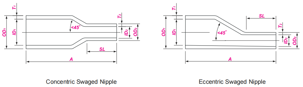
Concentric swage nipple: The centerlines of the two connected pipes are aligned in a straight line. This type is primarily used in vertical pipelines. In some vertical water supply or gas supply pipeline systems, concentric reducers ensure stable fluid flow in the vertical direction, reducing resistance and turbulence caused by changes in pipe diameter.
Eccentric swage nipple: Primarily used in horizontal pipelines. For example, in horizontal oil transportation pipelines, eccentric reducers can be adjusted to accommodate height differences between pipes as needed to meet process requirements or avoid interference with other equipment. Additionally, in applications requiring control of fluid flow direction and velocity, eccentric reducers can play a unique role.
In small-diameter pipelines (DN50 and below), swage nipples are often used to replace reducer fittings for pipeline diameter changes. Compared to reducer fittings, swage nipple offer better cost-effectiveness and installation convenience in certain situations, meeting the flexible and varied design requirements of small-diameter pipeline systems.
MSS SP – 95 Swage Nipple Dimensions
| Nominal Size | OD at End | Length of Small End | End to End | Nominal Size | OD at End | Length of Small End | End to End | |||
| DN | NPS | OD X OD | SL min | A | DN | NPS | ODX OD | SL min | A | |
| 8×6 | 1/4×1/8 | 13.7×10.3 | 20 | 57 | 65×6 65×8 65×10 65×15 65×20 65×25 65×32 65×40 65×50 | 21/2×1/8 21/2×1/4 21/2×3/8 21/2×1/2 21/2×3/4 21/2×1 21/2×11/4 21/2×11/2 21/2×2 | 73.0×10.3 73.0×13.7 73.0×17.1 73.0×21.3 73.0×26.7 73.0×33.4 73.0×42.2 73.0×48.3 73.0×60.3 | 22 22 22 25 25 30 30 40 40 | 178 | |
| 10×6 10×8 | 3/8×1/8 3/8×1/4 | 17.1×10.3 17.1×13.7 | 20 20 | 64 | ||||||
| 15×6 15×8 15×10 | 1/2×1/8 1/2×1/4 1/2×3/8 | 21.3×10.3 21.3×13.7 21.3×17.1 | 20 20 20 | 70 | ||||||
| 20×6 20×8 20×10 20×15 | 3/4×1/8 3/4×1/4 3/4×3/8 3/4×1/2 | 26.7×10.3 26.7×13.7 26.7×17.1 26.7×21.3 | 20 20 22 22 | 76 | ||||||
| 80×6 80×8 80×10 80×15 80×20 80×25 80×32 80×40 80×50 80×65 | 3×1/8 3×1/4 3×3/8 3×1/2 3×3/4 3×1 3×11/4 3×11/2 3×2 3×21/2 | 88.9×10.3 88.9×13.7 88.9×17.1 88.9×21.3 88.9×26.7 88.9×33.4 88.9×42.2 88.9×48.3 88.9×60.3 88.9×73.0 | 22 22 22 25 25 30 30 40 40 40 | 203 | ||||||
| 25×6 25×8 25×10 25×15 25×20 | 1×1/8 1×1/4 1×3/8 1×1/2 1×3/4 | 33.4×10.3 33.4×13.7 33.4×17.1 33.4×21.3 33.4×26.7 | 20 20 22 22 22 | 89 | ||||||
| 32×6 32×8 32×10 32×15 32×20 32×25 | 11/4×1/8 11/4×1/4 11/4×3/8 11/4×1/2 11/4×3/4 11/4×1 | 42.2×10.3 42.2×13.7 42.2×17.1 42.2×21.3 42.2×26.7 42.2×33.4 | 20 20 22 22 25 25 | 102 | ||||||
| 90×6 90×8 90×10 90×15 90×20 90×25 90×32 90×40 90×50 90×65 90×80 | 31/2×1/8 31/2×1/4 31/2×3/8 31/2×1/2 31/2×3/4 31/2×1 31/2×11/4 31/2×11/2 31/2×2 31/2×21/2 31/2×3 | 101.6×10.3 101.6×13.7 101.6×17.1 101.6×21.3 101.6×26.7 101.6×33.4 101.6×42.2 101.6×48.3 101.6×60.3 101.6×73.0 101.6×88.9 | 22 22 22 25 25 30 30 40 40 40 40 | 203 | ||||||
| 40×6 40×8 40×10 40×15 40×20 40×25 40×32 | 11/2×1/8 11/2×1/4 11/2×3/8 11/2×1/2 11/2×3/4 11/2×1 11/2×11/4 | 48.3×10.3 48.3×13.7 48.3×17.1 48.3×21.3 48.3×26.7 48.3×33.4 48.3×42.2 | 20 20 22 25 25 25 25 | 114 | ||||||
| 50×6 50×8 50×10 50×15 50×20 50×25 50×32 50×40 | 2×1/8 2×1/4 2×3/8 2×1/2 2×3/4 2×1 2×11/4 2×11/2 | 60.3×10.3 60.3×13.7 60.3×17.1 60.3×21.3 60.3×26.7 60.3×33.4 60.3×42.2 60.3×48.3 | 20 22 22 25 30 30 30 30 | 165 | ||||||
| 100×8 100×10 100×15 100×20 100×25 100×32 | 4×1/4 4×3/8 4×1/2 4×3/4 4×1 4× 11/4 | 114.3×13.7 114.3×17.1 114.3×21.3 114.3×26.7 114.3×33.4 114.3×42.2 | 25 25 25 30 30 40 | 229 | ||||||
Swage Nipple Weight Chart in kg
| DN | NPS | SCH 10 | SCH 30 | STD | SCH 40 | XS | SCH 80 | SCH 160 | XXS |
| 8 | 1/4 | 0.03 | 0.03 | 0.03 | 0.03 | 0.04 | 0.04 | – | – |
| 10 | 3/8 | 0.04 | 0.04 | 0.05 | 0.05 | 0.07 | 0.07 | – | – |
| 15 | 1/2 | 0.07 | 0.08 | 0.09 | 0.09 | 0.11 | 0.11 | 0.13 | 0.17 |
| 20 | 3/4 | 0.09 | 0.11 | 0.12 | 0.12 | 0.16 | 0.16 | 0.21 | 0.27 |
| 25 | 1 | 0.18 | 0.19 | 0.21 | 0.21 | 0.28 | 0.28 | 0.36 | 0.47 |
| 32 | 1-1/4 | 0.27 | 0.28 | 0.33 | 0.33 | 0.44 | 0.44 | 0.55 | 0.76 |
| 40 | 1-1/2 | 0.35 | 0.39 | 0.44 | 0.44 | 0.59 | 0.59 | 0.79 | 1.06 |
| 50 | 2 | 0.62 | 0.71 | 0.86 | 0.86 | 1.19 | 1.19 | 1.76 | 2.13 |
| 65 | 2-1/2 | 0.9 | 1.37 | 1.48 | 1.48 | 1.95 | 1.95 | 2.55 | 3.48 |
| 80 | 3 | 1.26 | 1.93 | 2.2 | 2.2 | 2.98 | 2.98 | 4.16 | 5.39 |
| 90 | 3-1/2 | 1.45 | 2.22 | 2.64 | 2.64 | 3.63 | 3.63 | – | – |
| 100 | 4 | 1.84 | 2.84 | 3.53 | 3.53 | 4.91 | 4.91 | 7.37 | 9.02 |
| 125 | 5 | 3.1 | – | 5.83 | 5.83 | 8.29 | 8.29 | 13.2 | 15.4 |
| 150 | 6 | 4.04 | – | 8.25 | 8.25 | 12.4 | 12.4 | 19.7 | 23.3 |
| 200 | 8 | 6.35 | 11.7 | 13.5 | 13.5 | 20.5 | 20.5 | 35.2 | 34.2 |
| 250 | 10 | 10.2 | 18.7 | 22.1 | 22.1 | 29.8 | 35.1 | 63.0 | 56.7 |
| 300 | 12 | 14.0 | 25.4 | 28.8 | 31.1 | 38.0 | 51.5 | 93 | 72.8 |
Nomenclature According to the Ends of the Reduced Nipple
Bevel of Both Ends ( BBE)
Plain of Both Ends ( PBE)
Thread of Both Ends ( TBE)
Bevel of Large End / Plain of Small End ( BLE/PSE)
Bevel of Large End / Thread of Small End ( BLE/TSE)
Plain of Large End / Thread of Small End ( PLE/TSE)
Plain of Large End / Bevel of Small End ( PLE/BSE)
Thread of Large End / Bevel of Small End ( TLE/BSE)
Bevel of Large End / Thread of Small End ( BLE/TSE)

Difference between Swage Nipple and Reducer
Although swage nipple and reducer fittings both belong to the category of pipe size transition fittings, they differ significantly in structure and application. swage nipple are forged short pipe fittings with a shorter length, primarily used in small-diameter pipes. They often replace reducer joints to achieve size transitions and offer diverse connection methods, including beveled edges, threads, and flat ends, making them suitable for high-pressure and frequent disassembly scenarios.
Reducers, on the other hand, are typically formed through stamping or welding, with relatively longer lengths, and are suitable for large-diameter pipeline systems. They are divided into concentric and eccentric types, primarily used for transition connections between pipelines of different diameters. In fluid transportation, they prioritize minimizing resistance, with welding being the primary installation method. They are widely applied in large-scale pipeline engineering projects such as chemical and water conservancy industries.
Applications
Oil and gas pipeline modification or repair
High and low pressure system interface connections
Connection of instrumentation equipment to main pipelines
Temporary connections and transition joints in industrial installations
Connection between hydraulic systems and pipeline fittings